tinyGS
· tinyGS Community · tutorial · 5 min read
How to Build a 1/4 Wave DIY Ground Plane Antenna for 433MHz
A step-by-step guide to building a high-performance, low-cost omnidirectional antenna for your tinyGS station using basic copper wire.
If you followed our equipment guide, you already know that the stock whip antenna included with most LoRa boards is highly discouraged and will likely receive nothing from orbit. To truly track satellites without breaking the bank, building a 1/4 Wave Ground Plane Antenna is the perfect weekend project.
It is inexpensive, robust, and offers an outstanding balance of satellite reception and portability. Let’s build one tuned specifically for the tinyGS network frequency (433 MHz).
Technical Concept & Dimensions
A 1/4 wave ground plane antenna consists of one vertical driven element (the radiator connected to the center pin of your coax) and four radial elements bent downwards at a 45-degree angle. Bending the radials shifts the antenna’s impedance close to 50 Ohms, matching your tinyGS receiver perfectly without needing complex matching networks.
To calculate the precise lengths of the elements for 433.5 MHz, we use the formulas featured in the M0UKD Antenna Calculator:
- Vertical Driven Element (Radiator): ~16.5 cm (6.5 inches)
- Ground Radials (4 pieces): ~18.1 cm (7.1 inches)
💡 Pro-Tip from the Specs: Always cut your wires 10% to 20% longer than the theoretical calculation. It is much easier to trim a wire down using a NanoVNA analyzer during tuning than it is to add wire back if it is too short! Thicker wire (like 14-gauge / 2mm² copper) will also provide a slightly wider bandwidth.
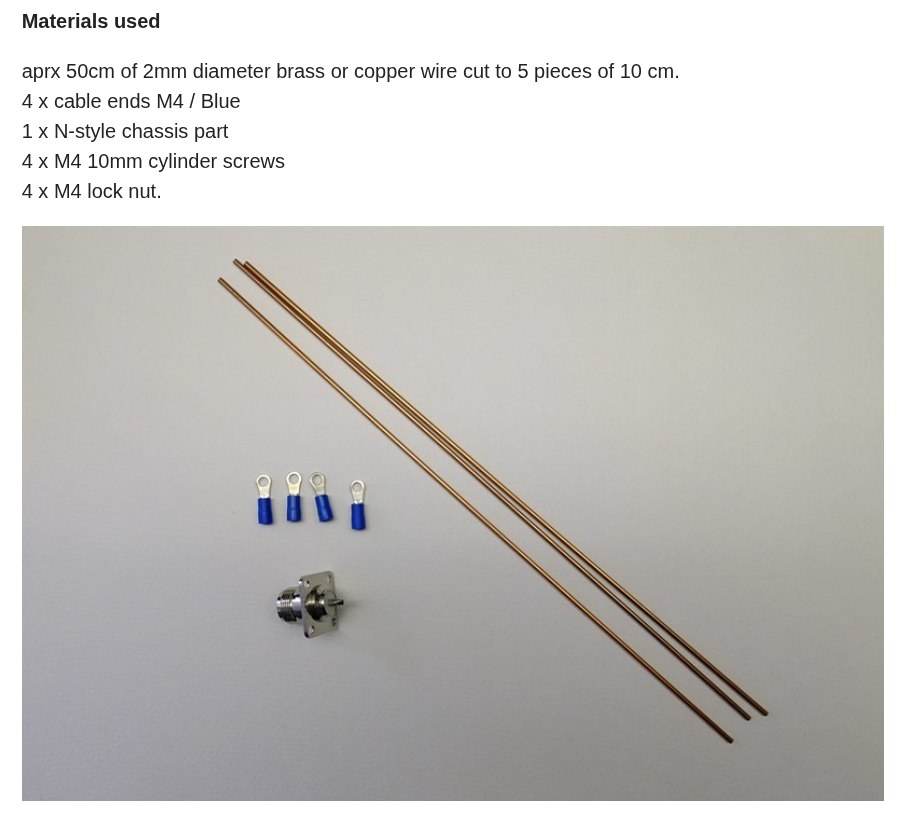
Materials Needed
- Chassis Mount Connector: An SO-239 (UHF Female) or an N-Type Female flange-mount connector with 4 pre-drilled corner holes.
- Crucial Selection: Buy a connector with a Teflon (PTFE) dielectric. Cheap plastics will melt instantly and ruin the pin alignment when you apply the heat of the soldering iron.
- Wire: ~1 meter of 12 or 14 AWG solid copper wire (standard household electrical wire works beautifully).
- Hardware: Four small M3 bolts and nuts to secure the radials to the flange holes.
- Tools: Soldering iron, solder, wire cutters, and pliers.
Step-by-Step Construction
Step 1: Preparing the Driven Element
Strip the insulation off your copper wire. Straighten a piece and insert it into the center cup/pin of your SO-239 or N connector. Solder it generously.
🛠️ Pro-Tip: Thread your chassis connector onto a spare cable or male connector before soldering. The extra metal acts as a heat sink and guarantees the center pin stays perfectly aligned if the inner dielectric softens from the heat.
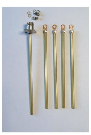
Step 2: Attaching the Ground Radials
Take four separate pieces of wire (cut around 19-20 cm to leave room for trimming). Loop one end of each wire tightly or loop them directly around the four mounting bolts on the corner flange. Secure them tightly using your nuts and bolts.
Step 3: Bending the Radials
Using your pliers, bend all four ground radials downward at roughly a 45-degree angle. This physical angle is what transforms a standard vertical antenna into a balanced 50-Ohm load.
Step 4: Trimming to Frequency
Measure exactly 16.5 cm from the top edge of the connector base to the tip of your vertical wire and clip off the excess. Next, measure exactly 18.1 cm for each of the four radials starting from the bolt holes, and clip them even.
Your structural assembly is now complete!
Weatherproofing (The Most Critical Step)
Since your DIY antenna will live permanently outside on top of a mast, waterproofing is non-negotiable. While the antenna itself costs pennies and can easily be replaced, high-quality coaxial cable is expensive.
The Hidden Danger of Water Ingress
Water entering the coaxial cable will slowly corrode the copper shielding, shift the system’s impedance, and ruin your signal attenuation. This issue is notoriously hard to diagnose because your station will suffer from missed packets only while it rains, seemingly fixing itself a day after the sun comes out.
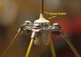
Sealing the Top Dielectric
Apply a robust layer of epoxy or heavy-duty hot glue right around the base of the vertical element where it meets the connector’s internal insulation. This completely seals the dielectric path, stopping moisture from traveling down into the cable structure.
Protecting the Coaxial Connection
Once you mount the antenna outdoors and screw in your main feedline cable, wrap the entire mated RF connection tightly using coaxial mastic tape (like 3M 2228) or self-amalgamating electrical tape. Do not skimp on this step; the joint must be entirely airtight.
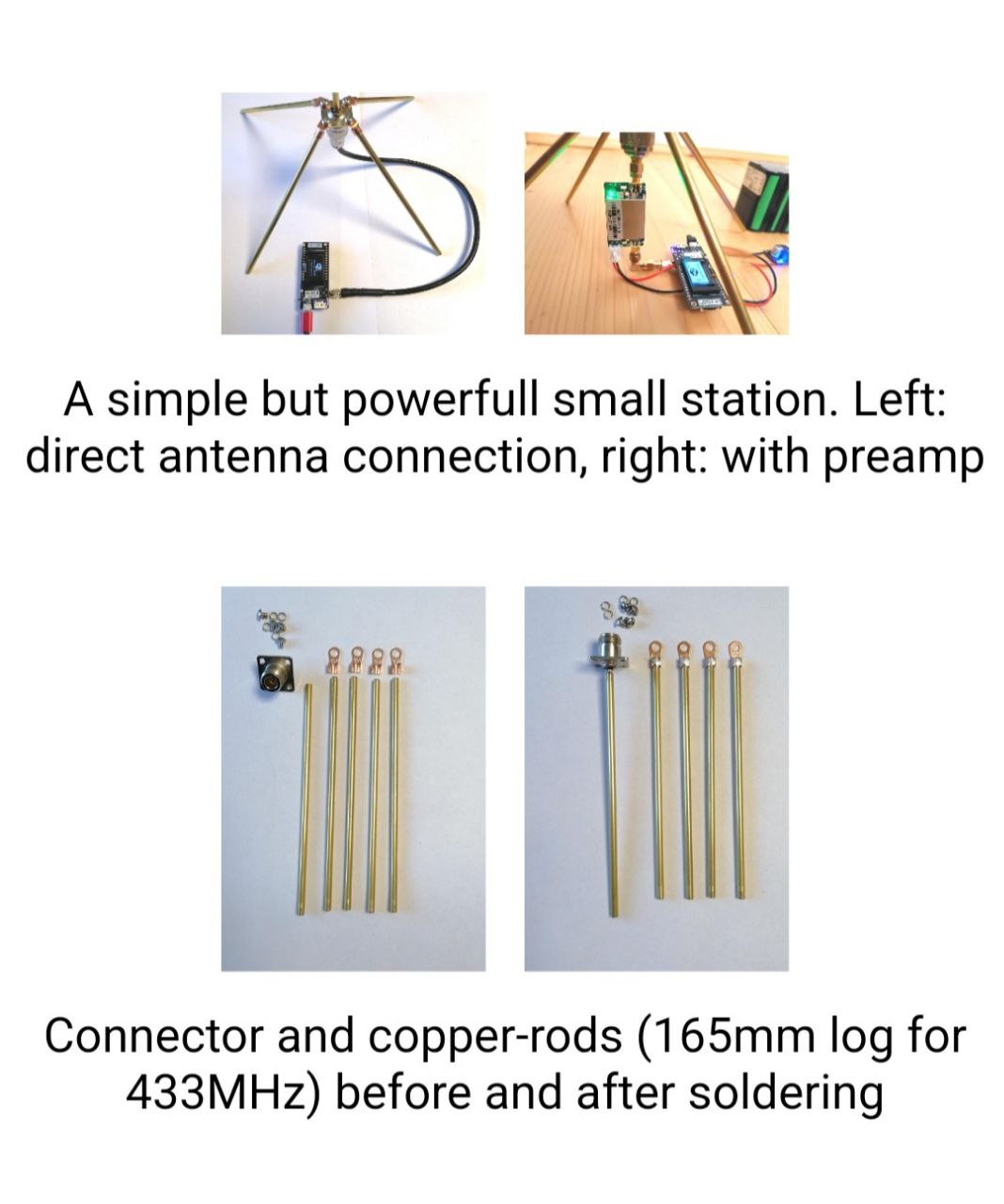
Visual Examples from the Field
Here is how other “Tiners” in the network have successfully deployed this exact design:
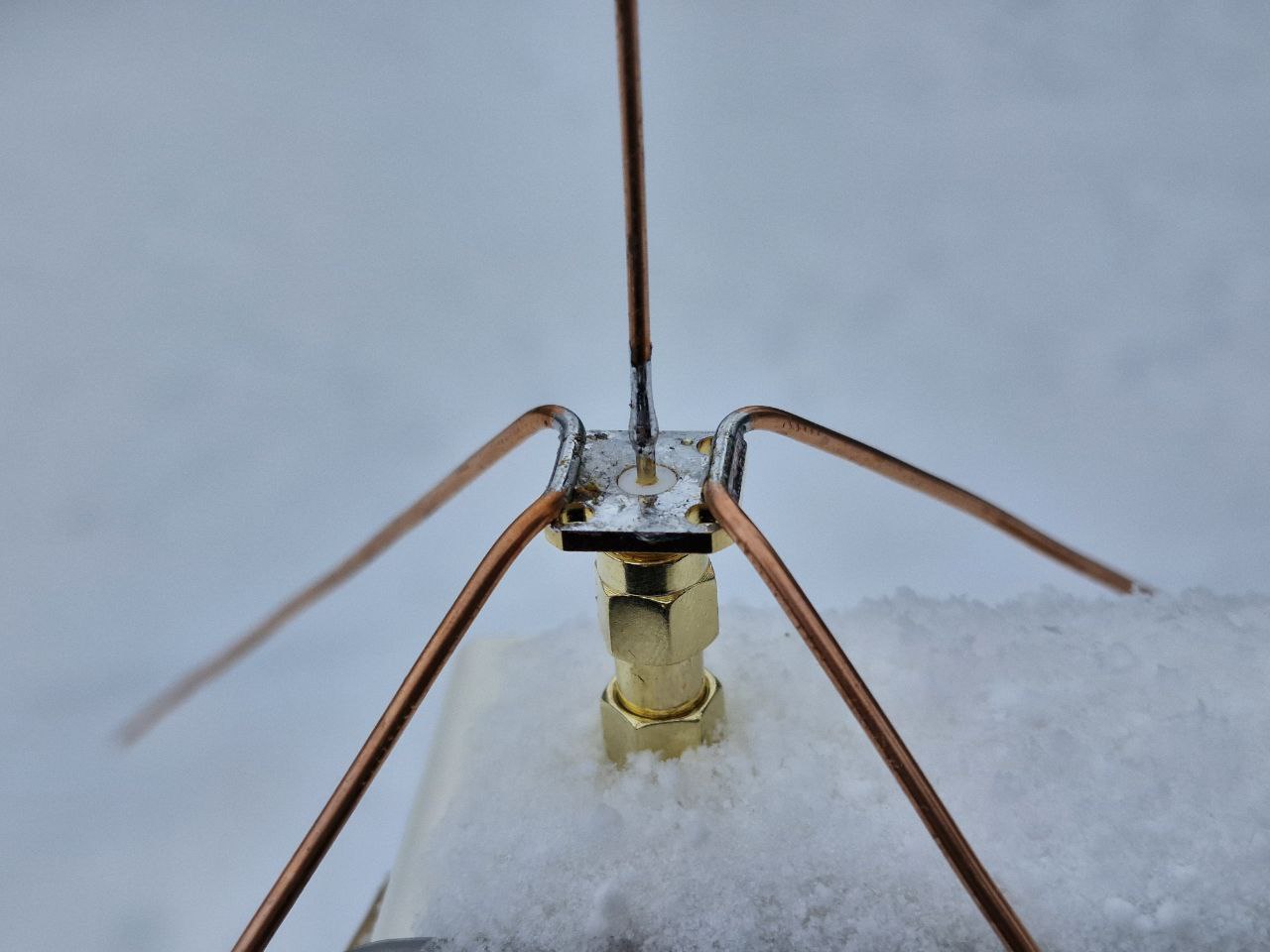
Example A: Compact N-Type Direct Mount
A super clean build utilizing a low-loss N-Type panel connector, perfectly trimmed and ready to accept a pigtail adapter.
Example B: Structural Mast Mounting
Using a simple metal angle bracket or U-bolt attached to the flange holes allows you to mount the antenna easily to any outdoor pole or balcony rail. 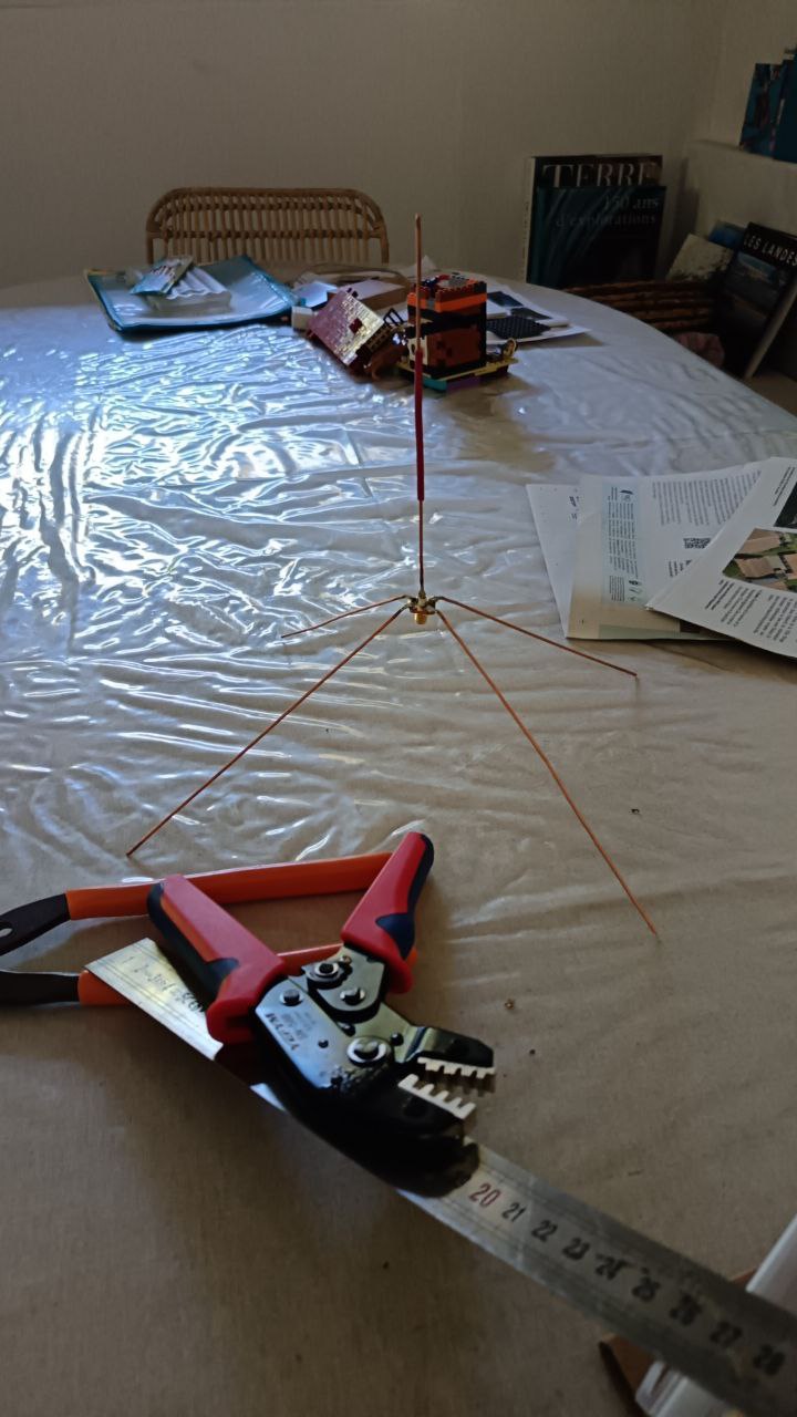
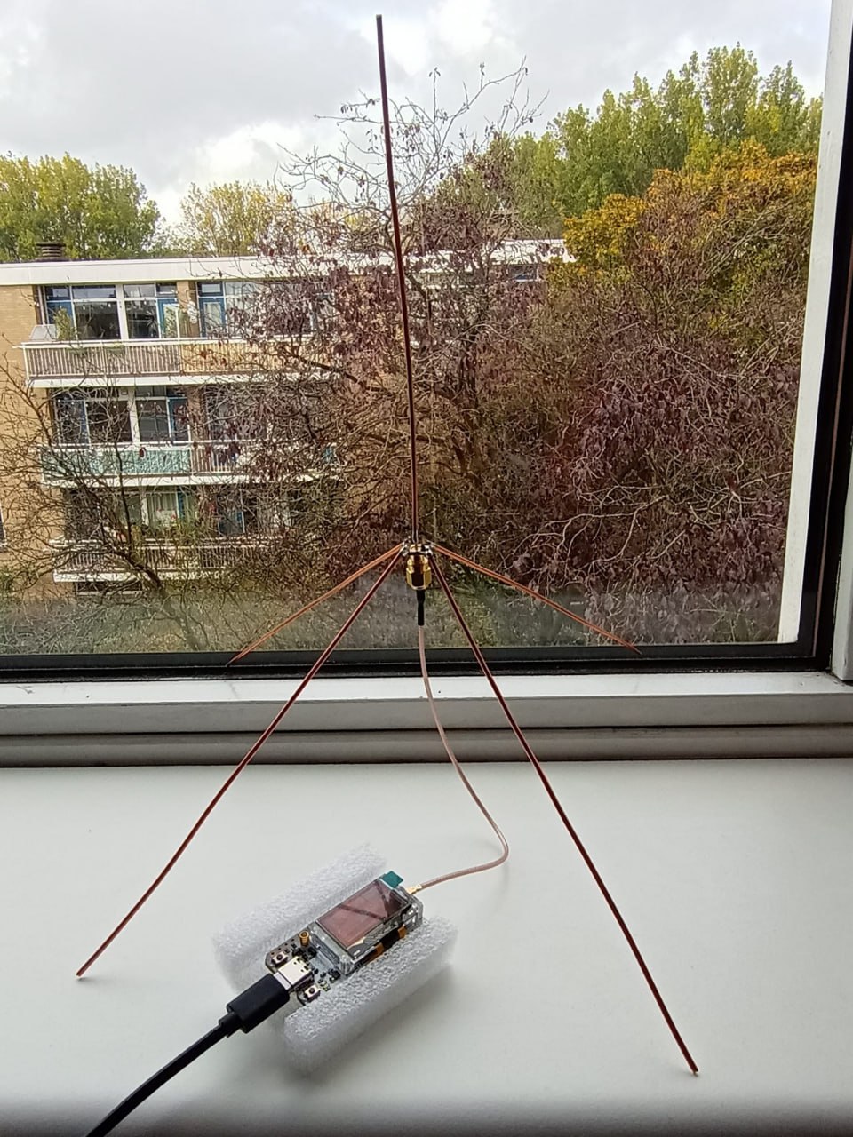
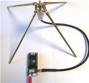
Example C: The Final Outdoor Setup
A field-tested station showing the 1/4 wave antenna elevated and clear of ground obstacles, providing an optimal 360-degree horizon view for picking up low-power satellite passes. 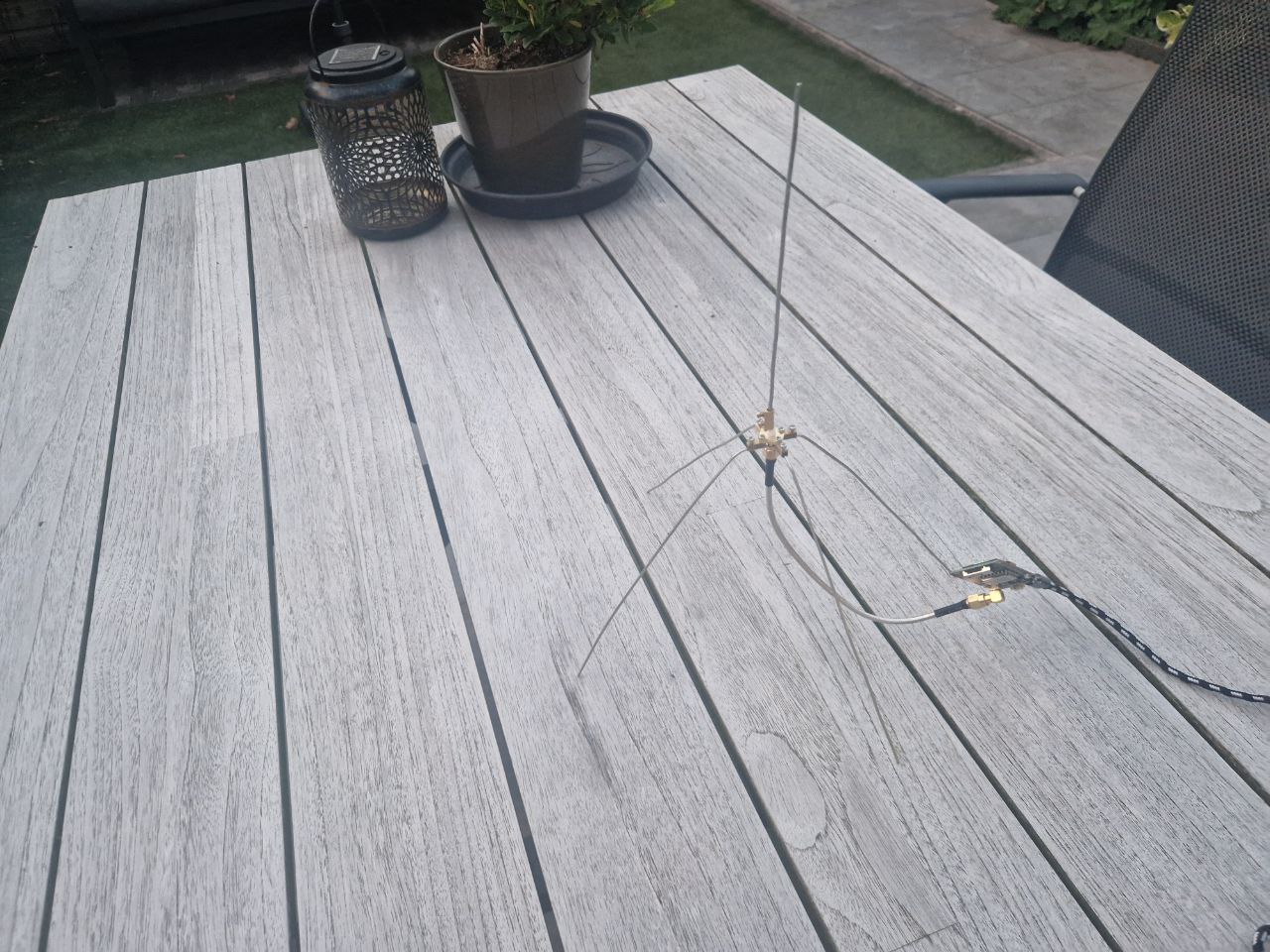
Next Steps 🛠️
With your high-gain DIY antenna built and sealed against the elements, connect it to your station and check your tinyGS dashboard. You should see your first automated satellite packets rolling in shortly!
Have a custom variant of this antenna or a smart mounting hack? Share it in our community topic!